What Is a Diesel Transfer Pump and How Does It Work?
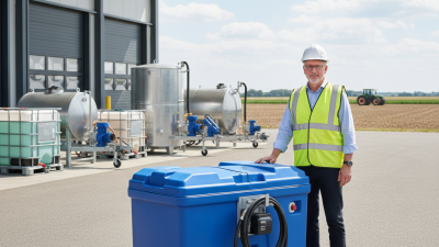
A diesel transfer pump moves diesel fuel from one container to another safely and efficiently. It commonly serves storage tanks, generators, farm equipment, construction machinery, and service vehicles. Unlike an engine injection pump, it does not create the high pressure required for combustion. Its main task is simpler: deliver clean fuel at a controlled flow rate.
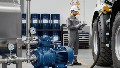
The basic process begins when an electric motor or engine-driven mechanism rotates the pump. Inside, gears, vanes, or a diaphragm create low pressure at the inlet. Atmospheric pressure then pushes diesel through the suction hose. The pump carries the fuel through its chamber and sends it toward the outlet hose, filter, or receiving tank. Small details matter. A blocked filter, loose connection, or damaged seal can reduce flow and introduce air.
In practical maintenance work, operators usually check hose condition, grounding, filter cleanliness, and automatic shutoff functions. They also confirm that the pump matches the fuel type, voltage, flow demand, and tank arrangement. A diesel transfer pump may look like a simple piece of equipment, but poor installation can cause leaks, inaccurate filling, or premature wear. That part is often underestimated.
This guide explains the main pump designs, internal working principles, important components, and common performance problems. It also considers safe operation and routine inspection. No pump works perfectly in every setting. Temperature, fuel quality, hose length, and elevation can change its behavior. Understanding those limits helps users choose equipment more carefully and maintain it with greater confidence.
Diesel Transfer Pump Basics: 10–60 GPM Systems and Core Components
What Is a Diesel Transfer Pump and How Does It Work?
Diesel Transfer Pump Basics: 10–60 GPM Systems and Core Components
A diesel transfer pump moves fuel from a storage tank to equipment, vehicles, or another approved container. Most systems deliver between 10 and 60 gallons per minute. The correct flow rate depends on tank size, equipment demand, hose length, and elevation. A 10 GPM pump suits slower refueling tasks. A 60 GPM system serves larger fleets and high-use operations.
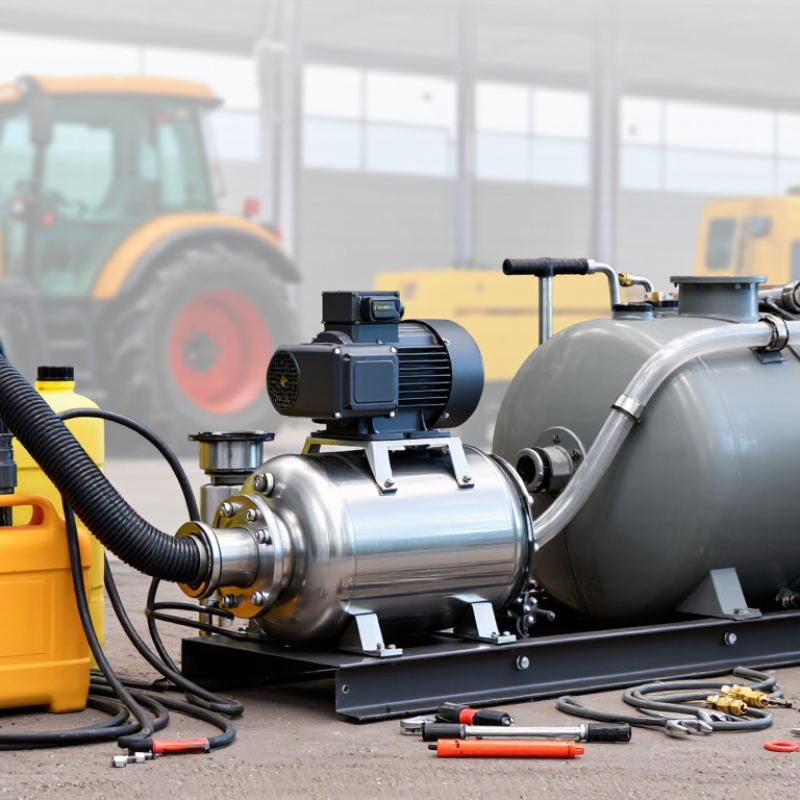
The pump assembly usually includes an electric motor, pump head, inlet strainer, pressure relief valve, meter, hose, and dispensing nozzle. The motor turns the pump mechanism, creating suction at the inlet. Diesel then passes through the strainer and travels through the discharge hose. The nozzle controls delivery at the outlet. A relief valve protects the system when flow becomes restricted. Small details matter here. A clogged strainer can make a powerful pump seem defective.
Technicians should verify fuel compatibility, electrical ratings, grounding, ventilation, and connection quality before operation. The hose must handle the system’s pressure and flow. Excessive bends can reduce performance. Keep the inlet line short and sealed against air leaks. Air intrusion often causes uneven flow, though it is easy to overlook. Flow meters also need periodic checking because displayed volume may drift over time. In real installations, the “perfect” 60 GPM rating may not appear at the nozzle. Filters, narrow fittings, and long hoses quietly reduce output. Reviewing these restrictions gives a more reliable sizing decision.
Diesel Transfer Pump Basics: 10–60 GPM Systems
This chart shows the theoretical time required to transfer 100 US gallons of diesel at common pump flow rates.
Actual transfer time can be longer because of hose length, filter restriction, nozzle size, elevation, temperature, and pump condition.
A typical diesel transfer system includes a pump, suction hose, discharge hose, fuel filter, check valve, meter, pressure-relief protection, and an automatic or manual nozzle.
How Diesel Moves: Suction, Pressurization, and Discharge Stages
What Is a Diesel Transfer Pump and How Does It Work?
A diesel transfer pump moves fuel from a storage tank to a vehicle, generator, or engine supply system. Its operation follows three practical stages: suction, pressurization, and discharge. During suction, the pump creates lower pressure inside its inlet chamber. Atmospheric pressure then pushes diesel through the pickup pipe. A tight connection matters here. Even a small air leak can reduce flow and make the pump sound rough.
During pressurization, rotating gears, vanes, or another displacement mechanism traps the fuel. The moving parts compress and guide diesel toward the outlet side. This pressure must match the system’s requirements. Excessive pressure may stress seals, hoses, or filters. Insufficient pressure can cause slow filling and unstable engine operation. The pump does not “pull” fuel in exactly as many people imagine; pressure differences do most of the work.
Tips: Keep the inlet strainer clean, inspect hoses for cracks, and check fittings before operation. Watch for unusual noise, pulsation, or visible leakage. A clear filter bowl can help reveal water or sediment, when the system includes one. Do not rely only on sound. Flow measurements and pressure readings provide better evidence. In practice, troubleshooting is not always neat. A weak battery, cold fuel, or a partially blocked vent can resemble pump failure, so each cause deserves a careful check.
Pump Types Compared: Vane, Gear, and Centrifugal Designs
A diesel transfer pump moves fuel from a tank to an engine, generator, or dispensing point. It supplies steady flow at moderate pressure. It is not the high-pressure injection pump. In service, an electric motor or engine drive turns the pumping element. Fuel enters through an inlet, passes the working chamber, and leaves through the outlet. Good installation includes a strainer, secure hoses, and a pressure-relief path. Small details matter.
Vane pumps use sliding blades inside a rotating chamber. The blades create changing spaces that draw in and push out diesel. They provide smooth flow and suit many general transfer duties. However, dry running can damage the blades quickly. Gear pumps trap fuel between gear teeth and the housing. They tolerate thicker fuel and maintain useful pressure across changing conditions. Their output can feel more pulsating. Worn clearances reduce performance, sometimes gradually enough to escape notice.
Centrifugal pumps accelerate fuel with a spinning impeller. They work best with clean, low-viscosity diesel and a consistent supply. Their flow changes noticeably when resistance increases. They also need proper priming in many installations. For routine transfer, vane or gear designs often offer better control. Yet that choice is not automatic. I would verify required flow, lift, viscosity, duty cycle, and filtration before selecting one. Real fuel conditions often challenge the neat comparison.
Sizing by Flow, Pressure, Viscosity, and Duty Cycle Requirements
What Is a Diesel Transfer Pump and How Does It Work?
A diesel transfer pump moves fuel from a tank to an engine, vehicle, or storage vessel. It creates flow by rotating an impeller, gear set, or diaphragm. The correct size depends on flow, pressure, viscosity, and duty cycle. Start with the duty. A pump delivering 40 liters per minute fills a 200-liter tank in about five minutes, before hose losses.
Measure the route. Required pressure must overcome vertical lift, pipe friction, meter resistance, and filter restriction. A pump rated for high pressure may still deliver poor flow through a narrow hose. ASTM D975 specifies No. 2-D diesel viscosity at 40°C between 1.9 and 4.1 mm²/s. Cold fuel can become thicker, increasing starting torque and reducing actual output. The U.S. Department of Energy’s Alternative Fuels Data Center lists diesel energy content near 128,488 Btu per gallon, but energy content does not determine pump capacity.
Duty cycle matters. Intermittent transfer allows cooling between fills, while continuous operation requires suitable motor, seal, and housing ratings. Select a pump that meets the target flow at the real operating pressure, not its maximum label value. In practice, this is where neat spreadsheets fail. Oversizing can increase heat, noise, and filter loading. Undersizing causes long fill times and motor strain. Leave a reasonable margin, then verify performance with a flow test at the coldest expected fuel temperature. The estimate may still need revision.
What Is a Diesel Transfer Pump and How Does It Work? — Sizing by Flow, Pressure, Viscosity, and Duty Cycle Requirements
Typical diesel transfer pump sizing ranges. Actual selection should account for hose length, elevation, filtration, fuel temperature, and system losses.
| Application |
Required Flow |
Pressure Requirement |
Fuel Viscosity
at 40°C |
Duty Cycle |
Typical Port Size |
Recommended Suction Lift |
Typical Motor Range |
| L/min |
US gal/min |
Differential |
Equivalent |
Light vehicle refueling
Cars, vans, and small generators |
20–40 |
5–11 |
2–4 bar |
29–58 psi |
2–6 cSt |
Intermittent
15–30 min/h |
¾–1 in |
≤2 m |
0.37–0.75 kW |
Fleet fueling
Multiple light-duty vehicles |
40–80 |
11–21 |
3–5 bar |
44–73 psi |
2–6 cSt |
Intermittent
30–45 min/h |
1–1¼ in |
≤3 m |
0.75–1.5 kW |
Construction equipment fueling
Excavators, loaders, and mobile machinery |
60–120 |
16–32 |
4–7 bar |
58–102 psi |
2–8 cSt |
Intermittent
30–60 min/h |
1¼–1½ in |
≤3 m |
1.1–2.2 kW |
Bulk tank transfer
Storage tank filling and fuel redistribution |
100–250 |
26–66 |
3–6 bar |
44–87 psi |
2–10 cSt |
Continuous
up to 8 h/day |
1½–2 in |
≤4 m |
2.2–5.5 kW |
Long-hose or elevated transfer
Extended piping, reels, and moderate elevation |
40–100 |
11–26 |
5–8 bar |
73–116 psi |
2–8 cSt |
Intermittent
up to 60 min/h |
1–1½ in |
≤2 m |
1.5–3.0 kW |
Cold-weather or higher-viscosity diesel
Low-temperature transfer conditions |
20–60 |
5–16 |
3–6 bar |
44–87 psi |
6–15 cSt |
Intermittent
15–30 min/h |
1–1¼ in |
≤1.5 m |
0.75–2.2 kW |
Selection note: Select a pump based on the flow available at the required differential pressure, not on the pump’s zero-pressure maximum flow. Allow additional capacity for filters, meters, check valves, hose friction, elevation, and startup conditions.
Safety Standards: NFPA 30, UL 79, Grounding, Filtration, and Shutoff
A diesel transfer pump moves fuel from a storage tank to equipment through controlled pressure. Safety begins with the installation, not the motor. NFPA 30 addresses flammable and combustible liquid storage, dispensing, ventilation, and ignition control.
Its 2022 fire-loss report recorded 1,504,500 U.S. fires and $18.1 billion in property damage.
That figure is not diesel-specific, but it shows why small fuel systems deserve serious controls.
UL 79 covers power-operated pumps and dispensing equipment for petroleum liquids, where its scope applies.
A compliant pump should have suitable electrical components, protected wiring, and clear identification. Grounding is equally practical.
Bond the tank, pump, piping, and receiving vehicle before transfer begins.
Do not trust an earth rod alone. Static electricity can remain the hidden weakness.
Filtration protects both equipment and fuel quality.
A water-separating filter, correctly sized for flow, can capture water and damaging particles before they reach an engine. The micron rating should match the engine maker’s requirements, not guesswork.
Shutoff protection needs equal attention.
Use an accessible emergency stop, automatic overfill control, and a nozzle that stops flow when the receiving tank is full.
NFPA 30 requirements can vary with tank type and location, so the authority having jurisdiction should review the layout.
A checklist helps, but it can still miss a loose bonding cable or a blocked filter.
That is the uncomfortable part. Safety depends on inspection discipline, not equipment labels alone.
(Sources: NFPA, Fire Loss in the United States During 2022; NFPA 30; UL 79.)